IMS PCBs — composition, benefits and manufacturing

What is an IMS PCB?
An IMS PCB (Insulated Metal Substrate PCB) also known as metal core PCB (MCPCB) is a type of printed circuit board that incorporates a thick metal layer as the base substrate or core material. The most common metals used are aluminum, copper or alloy materials.
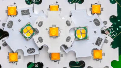
The metal core acts as a thermal conductor and heat spreader. It provides superior heat dissipation capabilities compared to standard PCB substrates like FR4 glass epoxy. This enables effective cooling of high–power electronics and devices that generate substantial heat like LEDs, power modules, laser diodes, and RF amplifiers.
The metal substrate is first coated with a thin dielectric layer, typically a polymer film, which electrically insulates the metal plate. On top of this is laminated a thin layer of copper, which is then photolithographically processed to produce the circuit traces, pads, vias, and other conductive features required for the metal core circuit boards.
The dielectric layer electrically isolates the bottom metal plate from the top conductive copper traces, while facilitating efficient thermal conductivity between the two layers. This allows the metal core to act as an internal heat sink, rapidly conducting heat laterally across the PCB and away from hot spots.
Key properties and benefits of an IMS PCB
There are several notable benefits that IMS PCBs provide over conventional FR4 PCB substrates:
Thermal management process
The superior thermal conductivity of the insulated metal substrate allows rapid lateral conduction and dissipation of heat across the PCB. This prevents localized hot spots under components. For example, aluminum has a thermal conductivity around 200 W/mK, compared to just 0.25 W/mK for standard FR4. Copper is even better with an increased thermal conductivity around 400 W/mK. This enables superior thermal resistance, ideal for LEDs, power devices, laser diodes, RF modules and other heat generating electronics.
Reliability
The coefficient of thermal expansion (CTE) of the metal core is much lower than FR4. This reduces mechanical stresses from thermal cycling. This makes an IMS PCB less prone to warping and fracturing over time under repeated heating/cooling. It also reduces solder joint fatigue and failures.
Current capacity
The high electrical conductivity of the thick metal core produces very low impedance. Excellent power distribution minimizes voltage drops across the PCB at high currents. This allows higher continuous current flow without overheating, ideal for power electronics.
Other properties
- Good physical strength and ruggedness.
- Metal cores can shield and contain electromagnetic interference (EMI).
- Wide range of dielectric materials available, including ceramic, flexible and high temperature types.
In summary, the metal core gives an IMS PCB superior thermal management, reliability and current capacity compared to standard PCB materials. This makes them ideal for cooling LED lighting, power devices, RF amplifiers and other demanding electronic applications. The tradeoff for the thermal resistance is higher cost.


Typical IMS PCB materials and construction
While specific designs vary, an IMS PCB generally consist of:
Metal core — Forms the metal substrate with thickness from 0.8mm to 6mm. Copper and aluminum are most common. Copper provides excellent thermal conductivity while aluminum is lightweight and cost-effective.
Dielectric layer — Thin insulation layer applied to the metal core, typically 50-150µm thick. The thickness and type of the dielectric is one of the most important features when it comes to the IMS PCBs because has direct influence of the heat dissipation level, measured in W/mK.
The dielectric layer is mainly built by epoxy-/polyimide-reinforced with woven glass and conductive filler. It acts as bonding glue between the copper layer and metal base and also has an isolation function.
Copper foil — 18-70μm layer of copper laminated to the dielectric and etched to form the circuit traces based on the PCB design.
Protective coating — Immersion gold, ENIG, OSP or other surface finish protects the copper traces from oxidation and enhances soldering.
Solder mask layers — Epoxy layer that coats the PCB surface providing electrical insulation and mechanical protection.
SMD components — Surface mount devices like resistors, capacitors, LEDs and ICs mounted by soldering to the circuit traces.

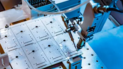
Steps in manufacturing IMS PCBs
Fabricating custom IMS boards involves precision processes including:
Materials bonding — The dielectric layer and copper foil are bonded to the insulated metal substrate through processes like spraying, electrophoretic deposition, anodization, or lamination.
Photolithography — A photoimageable mask is applied to the copper layer. Ultraviolet light exposes desired circuit patterns.
Etching — Chemical etching removes unwanted copper, leaving only the intended circuit traces protected by the mask.
Drilling — High accuracy CNC mechanical drilling forms all holes for component pins and vias.
Plating — Surfaces are plated with nickel, gold, tin or other metals to facilitate soldering and prevent oxidation.
Testing and QC — 100% electrical testing and visual inspection ensures quality and reliability.
Get your custom IMS PCBs from copperdot
When you need precision engineered IMS PCBs, choose copperdot as your procurement service. As IMS PCB specialists, we offer affordable and durable boards with 1-2 layer circuits built on metal cores of copper or aluminum.
Our automated sourcing and rigorous quality control ensures your finished boards are delivered on time and to your exact specifications. Contact us today for a fast quote or to discuss your next project!
FAQ
IMS PCBs are characterised above all by significantly better heat dissipation. The metal core acts as a large cooling surface. In addition, IMS are less susceptible to thermal expansion and mechanical stress. They are therefore suitable for heat-intensive applications.
IMS PCBs are used wherever reliable heat dissipation is crucial. Typical examples are LED lighting, power electronics, telecommunications, automotive and medical technology.
Since metals have a higher thermal expansion than FR4, larger components and assemblies must be placed with more clearance to the edge. Hole spacing also differs. In general, the PCB manufacturer's design guidelines should be followed.
Yes, there are also flexible IMS PCBs, so-called “IMS-Flex”. However, the bending radius is limited by the thickness of the metal core. Ultra-thin flex MKLPs are therefore not feasible.