A complete guide to flex circuit boards and flexible PCBs (printed circuit boards)
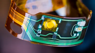
Flexible PCBs, also known as flex circuits or flexible printed circuit boards (FPCBs), are a type of printed circuit board that is thin, lightweight, and bendable. Unlike traditional rigid PCBs, flexible PCBs can bend and flex to fit mechanically challenging spaces and move dynamically in products. With the right design and materials, flexible PCBs offer many advantages over rigid boards in terms of size, weight, reliability, and function.

What is a flexible PCB?
A flexible PCB is a printed circuit board made of flexible polymer substrates such as polyimide or PET instead of traditional rigid substrates like FR-4. The conductive layers are made of extremely thin copper foil rather than thick copper sheets. The lack of glass-fiber reinforcement allows the board to flex and bend freely without damage.
Flexible PCBs can be single-sided flex circuits, which contain printed conductors on only one side, double-sided flex circuits with conductors on both sides, or multi-layer flex circuits, which have two or more conductive layers separated by flexible dielectric layers.
The flexible sections allow the circuit board to bend, twist, fold, and dynamically flex without breaking or cracking. This makes flexible PCBs ideal for fitting into tight, curved mechanical spaces and for dynamic flexing applications.
Key benefits and applications of flex circuits
There are many important reasons why an engineer may choose a flex PCB instead of a traditional rigid board:
Flexible
Flexible PCBs can bend, twist, and flex repeatedly to fit challenging 3D spaces, making it possible to integrate them easily into curved or dynamic surfaces.
Lightweight
Flex circuits weigh 80 to 90% less than rigid PCBs. Flexible circuits with thin material layers greatly reduce weight.
Thin
As thin as 25 microns, saving space in tight areas. Taking up less space helps reduce the size of electronics.
Durable
Flexible PCBs can withstand millions of dynamic flex cycles without the conductive traces cracking. This makes flex PCBs ideal for moving components.
Reliable
Excellent for high vibration or shock environments. Flexible boards can handle shaking and impacts better than brittle rigid boards.
Customizable
Flexible circuits can be bent, folded, or twisted into any 3D shape needed, enabling the creation of unique form factors and ergonomics.
Scalable
From simple to highly complex layouts, flex PCBs can support everything from minimalist wearables to advanced multi-layer boards.


Flexible vs. rigid-flex PCBs
While a flexible PCB is made entirely from thin, bendable materials, a rigid-flex PCB combines flexible circuit sections along with rigid board sections for structural support .
Rigid-flex PCBs make it possible to integrate flexible connections between multiple rigid PCBs all in a single unified board. This eliminates cables while providing a robust structure.
Common rigid-flex applications include folding laptops, cell phones, servomotors, robotic arms, and advanced medical devices. The rigid sections provide mounts for components while the flex areas connect multiple rigid zones.
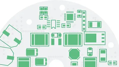
Flexible PCB materials and construction
Several key material technologies make flexible PCBs possible:

Flexible substrate films
The most common base material for flexible substrates is polyimide film. Other substrate options include PET and PEN. These plastic films provide the necessary flexibility, strength, and heat resistance up to 200°C. Polyimide films are typically 1 to 3 mil (25 to 75 microns) thick, but can also be thinner for tight bend radiuses. The flexible substrates give flex PCBs their signature ability to bend dynamically.
Conductive layers
The conductive copper layers are made from rolled annealed copper foil, typically 12 to 35 microns thick. A thinner layer allows for tighter bending without cracking. The foil is commonly bonded to the substrate with acrylic or epoxy adhesives that are optimized for flexible circuits. This adhesive layer bonds the conductors securely during dynamic flexing.
Coverlay and solder mask
A coverlay or solder mask layer helps protect the thin copper conductors from damage. This layer covers the traces while leaving bonding pads exposed.
Stiffeners
Selected stiffeners made from materials like aluminum, FR4, Pl, or steel can be added to reinforce certain areas against bending. This allows for tailored flexibility across the circuit board.
Flexible adhesives
Adhesives are important for bonding the layers of multi-layer flex circuits into a unified stackup. The adhesion must remain reliable despite being exposed to constant dynamic flex stress.
Key flexible PCB design considerations
Designing a reliable, high-performing flexible PCB requires considering factors such as:
- Dynamic flex requirements: How tight to bend? In which directions? This impacts trace routing, materials, etc.
- Layer stackup: Determining the dielectric materials, copper weights, and layer counts to meet circuit needs. Fewer, thinner layers allow for tighter bends.
- High-frequency performance: Careful impedance control and routing for radio, timing, and digital signals.
- Component mounting: Special adhesives, solders, and underfills to strengthen connections on flexible substrates during motion.
- Creep and fatigue: Reinforcing high-stress areas against cracking with extra adhesive or stiffeners.
- Thermal design: Dissipating heat from components using thermal vias, copper planes, or added heat sinks.
Proper flexible PCB design is essential for optimizing durability, performance, and manufacturability. An experienced engineering team skilled in flex PCB design can ensure your project’s success.
The many benefits of flexible circuit boards
When designed well, flexible PCB technology enables innovative electronics and devices that would not be possible with rigid circuit boards. With the right expertise, flexible circuits offer valuable advantages:
Compact, low-weight design
Thin, compact construction reduces weight and frees up real estate for other components.
Unmatched flexibility
Bendability allows for creative form factors and integration that would be impossible with rigid technology.
Reliability
Withstands millions of flex cycles and resists failure due to vibration or shock.
Streamlined manufacturing
Low-cost, high-volume processing with excellent yields and quality.
Aesthetics and ergonomics
Smoothly fits product contours for a seamless look and feel.
For the right applications, flexible PCBs often provide the ideal circuit implementation solution when designed properly.
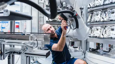
Flexible PCB capabilities with copperdot
copperdot provides full-service flexible PCB prototyping and production capabilities. Our engineering experts can help with design guidelines based on production restrictions and capabilities, streamlining your design for lean production, and choosing the most optimal solutions based on your needs and requirements.
We offer:
- Single, double, and multi-layer flexible circuits
- Complex rigid-flex designs
- Scaled production with excellent quality
- Rigorous testing and inspection in accordance with industry standards such as IPC-6013 and IPC-A-600
- Customized design support and DFM analysis from our flex experts
- Advanced flex and rigid-flex technologies
Contact our team today to discuss your next flex PCB project! We can help assess your design requirements and ensure your flexible circuit performs reliably for years to come.
Frequently asked questions about flexible PCBs
The main benefits of flexible PCBs include greatly reduced space requirements and lower weight due to their thin, lightweight construction; unmatched flexibility thanks to their ability to bend and flex; improved reliability through resistance to vibration/shock; streamlined manufacturing with excellent yields; and superior aesthetics/ergonomics by smoothly fitting product contours.
Flexible PCBs use thin, bendable substrate materials like polyimide instead of rigid materials like FR4. The conductive layers are made from thin rolled copper foil rather than thick sheets. This allows flexible PCBs to dynamically bend and flex without cracking.
Flexible PCBs are widely used in consumer electronics, automotive applications, aerospace applications, medical devices, and industrial equipment. Their ability to flex and fit into tight spaces makes them well-suited for these industries and areas of application.
Critical design factors include dynamic flex requirements, layer stackup, high frequency performance, component mounting strategies, creep/fatigue resistance, and thermal management. Consulting flex PCB design experts is highly recommended.